main page
The Plan
I wanted a moderately ambitious project with a deadline meant to counter perfectionism and loosing steam. I set on creating my own analog computer and created a set of milestones, budget, and time-frame of 3 weeks designing, 2 weeks assembling. A major problem was establishing a scope of how powerful I wanted the computer to be, as I'm using the project itself to learn about what is possible with the restrictions I set and didn't know about the finer details of these computers. Thankfully I extensively used anabrid's analog thing documentation for example programs, analog computer modules, and schematics of the analog thing (not sponsored) to get a feel for how large I wanted the project to be. Knowing and setting my project's scope, I completed the first milestone!

Trying and Buying
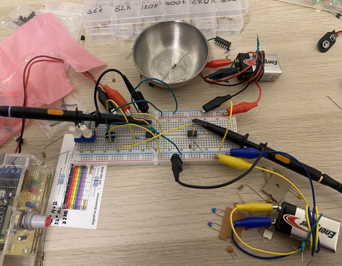
I had the parts on hand to test the computer modules I needed for my project, but the multiplier was out of the question to build due to it's complexity. With the multiplier chip cost (19$ per 1 multiplier!!) and the part count getting really high, I revised my scope to cut bloat. I also pivoted to buying a better variable power supply for the long-term instead of building a dedicated power supply. Back to testing, each of the modules were a bit of a challenge to get working but the multiplier and integrator modules beyond fought the most. Other components on the planned circuit need a specific voltage to work correctly, and the multiplier only completely works at higher voltages. After a lot of thinking/trial/error, I just decided the multiplier doesn't need to fully "work", and can get by producing 90% of it's range correctly :)))))). The integrator was working but the output was messy, and I tried to fix it from hitting the output limit of it's maximum/minimum. I realized a lot of noise was coming from the unideal test setup (unnecessary wire distance, bad connections, bad test inputs) and the second "problem" is supposed to happen in ideal integrators. With all module schematics functional, the second milestone is satisfied...
Board time Yipeee~
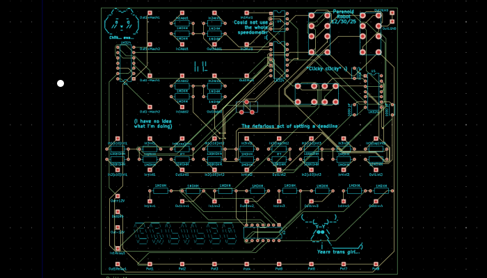
Designing the board was actually very easy. The program that I initially tried was genuinely unusable (pushy AI chatbots, forced account creation, always online, massive overhead, I digress) but people recommended KiKad. It's very rare today, but never has I used a program that was so straight forward/easy. Along with that, here's a 13 minute yt video which was the only resource I used learning the entire program, it's kinda magic!. After I designed the schematic, designed the board layout, wired the copper traces, and put memes on the board, I sent the files to an overseas board manufacturer JLCPCB (they ight). I had the choice to wait 2 weeks or pay +40$ shipping, so I waited 2 weeks. :3
Assembling phase!
Once my boards came in, I managed to solder all of the components to the board relatively quickly. My plan was to finish the board, design/create the panels for the patch cables to plug into, then wire the panels to the board. After that, I would connect the panels to spacers, the spacers to legs, and the legs to the panels again. Finally, I would make the patch cables. The rest of the project it realizing I neglected most non-electronic components and dug my grave many times over. The 77 jacks on the panels were friction fit with a hex-nut on the bottom, but it didn't have any good surface to torque against to tighten. Connecting the board to the panels needed 70+ individually cut wires to specific lengths. Soldering all of the wires from the panels to the board is exceptionally difficult when the wires in parallel are much stiffer than anticipated, and your using stranded wire through your board. Slight measurement adjustments earlier in design cascaded issues with the dials not fitting next to each-other, being very close to shorting components, and getting into the way of the legs. The legs were redesigned as I couldn't hold an m2 screw nut from inside the computer™️ and needed to accommodate against the unyielding strength of the connecting wires. The cardboard was a last minute addition because the legs were never actually able to be secured to the board. Did I tell you I still need to cut 20 more wires for the patch cables?
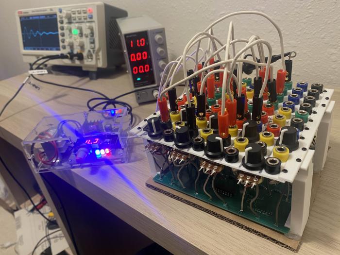
Oh, its finished? Testing showed its 100% functional?? Neat :D I'm very very happy with this project. It was incredibly fun and I learned a lot. I may have gone double over budget but I did finish the time constraint with a week to spare in assembly! not counting board shipping.